

=VG= SemlerPDX
-
Posts
4,877 -
Joined
-
Last visited
Content Type
Profiles
Forums
Events
Downloads
Gallery
Articles
AVCS Bug Reports (automated)
AVCS Bug Reports (manual)
VG Wiki
Blogs
Store
Everything posted by =VG= SemlerPDX
-

[Arma 3 Campaign] - Operation Déjà vu
=VG= SemlerPDX replied to =VG= The_Polish_Guy's topic in Arma III
I swear, I've seen this event before... (not sure if I will be in the mountains that weekend, will know more the closer we get - if available, I'll fill out some slot that needs filling, I'm not picky) -
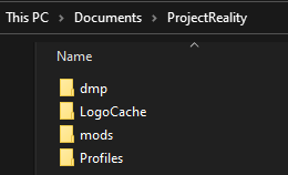
I assume you are running an Anti-Virus software beyond simply Windows Defender, and so you'll want to disable this software, and uninstall/reinstall PR. I am not sure if it is required to backup user profiles first, it's been a long time since I did this - your user profiles are located in 'My Documents\ProjectReality' The important part is that the Anti-Virus software deleted/quarantined files that PR needs to run. Not sure if you need to re-download fresh installer files, but if installing from files you already have fails (again), the next step would be to try downloading the files again while the Anti-Virus software is disabled. Once PR is properly installed, you can then run your Anti-Virus software and create an exception for the PR game to allow it to run without this software deleting files or putting them in quarantine. The way PR runs is a bit hacky and is no surprise that certain software would flag it as dangerous because it modifies files in memory for another software (BF2) in order to inject its own features and functionality, unlike other full conversion mods for games which openly release their source code for modders.

-
I would assume it is a false-positive related to anti-virus software. Please find that PRLauncher.log file and attach it here to a post, we can review it and discover exactly what is the issue, if it's not AV related. That would be the best place to start.
-
DIY - Wireless TrackClip Pro mod for TrackIR
=VG= SemlerPDX commented on =VG= SemlerPDX's blog entry in Profiles for VoiceAttack & other projects
Great work! So rewarding to free up some wires - glad you found my DIY build blog useful Best wishes and good luck with the battery holder! -
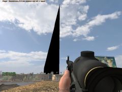 PR Bots firing dark matter mortars have opened up a tear in the fabric of PR Space-Time
 -
 Player Unknown: PR Stay inside the bubble!
 -
AVCS Voice Chat Artificial Intelligence Profile
=VG= SemlerPDX commented on =VG= SemlerPDX's file in VoiceAttack
 An occasional error may occur when contacting the OpenAI API through use of any application, including any VoiceAttack profiles using the OpenAI Plugin such as my own AVCS CHAT profile. The GetResponse phase (and the 'thinking' sound, in AVCS CHAT) may seem like it is looping infinitely, but in fact, it is waiting for a return from the OpenAI API. Eventually, it may result in no response (and any sounds just ending), or users being so confused that they restart VoiceAttack. I wanted users to know that they can just press the "Stop" button in VoiceAttack, closing and restarting is not required to end any looping sounds or a seemingly endless wait for a response from OpenAI API requests. Users can then immediately try their same input again - though note that any 'continuing session' will have ended due to the use of a "Stop" command, and the contextual memory of recent input/response pairs will be cleared, starting fresh again. The error which would appear in the "openai_errors.log" may look like this: ========================================================================== OpenAI Plugin Error at 2023-05-10 9:30:17 AM: System.Exception: OpenAI Plugin Error: Error at chat/completions (https://api.openai.com/v1/chat/completions) with HTTP status code: 429. Content: { "error": { "message": "That model is currently overloaded with other requests. You can retry your request, or contact us through our help center at help.openai.com if the error persists. (Please include the request ID a123456b7cdef890a12b3c456d789e0f in your message.)", "type": "server_error", "param": null, "code": null } } at OpenAI_VoiceAttack_Plugin.ChatGPT.<Chat>d19.MoveNext() --- End of stack trace from previous location where exception was thrown --- at System.Runtime.ExceptionServices.ExceptionDispatchInfo.Throw() at System.Runtime.CompilerServices.TaskAwaiter.HandleNonSuccessAndDebuggerNotification(Task task) at OpenAI_VoiceAttack_Plugin.OpenAIplugin.<PluginContext>d40.MoveNext() ========================================================================== Note on this 'overload' error from OpenAI API: In the whole of development and testing, and all of my calls to OpenAI API since I got beta access in December, I have never seen these 'overload' messages resulting in an API call failure. There is no way I could have anticipated it beyond the current exception handling which already occurs, however I also read the OpenAI Discord channels often, and we are NOT the only ones surprised and bothered by this seemingly brand new issue with the OpenAI API. This company has had to scale up faster than any new website in recent history - they went from a hundred thousand users to over ten million in less than two months, and I imagine each month of 2023 that goes by sees more and more tools such this allowing more and more users to access the OpenAI API, so they will need to scale it up accordingly. We just have to wait and deal with the 'overloads' that happen now and then. Just know it is not a fault of the plugin systems, the libaries I am using to access the OpenAI API, or anything to do with individual user accounts, and there is nothing we as users can change or do better. This is as good as it gets for now, and will only get better in time.
 -
Version 1.1
942 downloads
Artificial Intelligence Chat for VoiceAttack by SemlerPDX I am extremely proud to present my latest and greatest AVCS Profile for VoiceAttack yet, which allows for natural speaking conversations with a true artificial intelligence we can customize! It works by starting up a "conversation" with ChatGPT, first providing it with a System Prompt that helps refine how we want it to behave, and then it just sits in the background not listeneing, not sending anything to OpenAI or the ChatGPT API, until we wake it with a question, such as saying, "Hey VoiceAttack". It will respond, and wait for our question, and then (since it take a second to process using AI) a subtle 'thinking' sound plays until it responds in text-to-speech to our input. Then, it returns to listening for our next question or comment on what it just said - it remembers the context of our recent interactions in this manner, and if we simply do not respond, or use an existing VoiceAttack command, it will merely return to it's sleep loop until woke. But far more than just being another 'Alexa' or 'Siri' clone, AVCS CHAT uses the provided optional response variables that contain any hyperlinks or code blocks which were culled from the text-to-responses of ChatGPT, and automatically opens code examples in notepad or presents a list of any URL's we can open from a response. The included Chat System Menu allows us to view, edit, create, and delete System Prompts we can use at the beginning of a Chat Session - or set the default System Prompt to use. By default, the system prompt is one tailored for text-to-speech and brevity, although the "max tokens" are set to 2048 and it may override those instructions if asked for more complete details on the fly. Say, "Open the Chat System Menu" - much fun will be had! The beauty of this type of system is that we can tailor a perpetual background chat session we can resume anytime with a simple "Hey VoiceAttack" voice command, perhaps if the knowledge base of ChatGPT contains enough information about a game, we can craft a system prompt that makes it think it is an expert in that game and provides answers to guide players specifically as information relates to that game. This can establish a context at the start so that when you ask something that may also apply to the real world, you'll most likely get the response as it relates to that game. This can make for some rather entertaining and immersive conversations with a true AI we can call our own. Customize EVERYTHING! It's YOUR Personal AI! The profile has many "function" commands, which are not called by voice, but by the plugin or other commands. Their 'When I say' phrases are written such as "((VoiceAttack is...))" so that when these commands show up in the VoiceAttack Event Log, it feels correct like "((VoiceAttack is Speaking))" or "((VoiceAttack is Thinking))" .... each of these can and SHOULD be changed if desired, perhaps you call your profile a name like I do - change each 'When I say' phrase - and then inside the "Hey VoiceAttack" comand, change each of the text variables starting with "OpenAI_Command_" to reflect your altered command 'When I say' phrases: Even the "Hey VoiceAttack" command phrase could be "Hey Arnold" or however you would like to refer to your personal chat AI. Just make sure you follow comments in the profile, it's all quite simple and ready to use. FLOW EXAMPLE: User says, 'Hey VoiceAttack' (to awaken chat & global listening, if disabled) Profile says, "Yes?" User says anything - a VoiceAttack command, OR a question for ChatGPT (if not VoiceAttack command) Profile processes input and sends to ChatGPT and plays a subtle 'thinking' sound until ChatGPT responds Profile says, "(response from ChatGPT)" using text-to-speech (opening any code blocks in a notepad) - User says another question/etc. and ChatGPT responds again, OR user says nothing and input times out - ChatGPT enters 'Sleeping' loop until users says, 'Hey VoiceAttack' again to awaken it AVCS CHAT is designed to work as a Global Profile always ready in the background, but this is not required. =============== OPTIONAL WAYS TO USE THIS PROFILE =============== OPTION 1: Switch to the AVCS Voice Chat Artificial Intelligence Profile and say, "Hey VoiceAttack" to chat OPTION 2: Open Profile Options for any of your Profiles, select Include Commands from other profile: "AVCS Voice Chat Artificial Intelligence (latest version)" -or- OPTION 2b: Open VoiceAttack Options and select Global profiles, then Include Profile Commands from the profile: "AVCS Voice Chat Artificial Intelligence (latest version)" ========================================================= AVCS CHAT is powered by the OpenAI Plugin for VoiceAttack which I also created specifically so we all could make profiles like this. You will need to download and install this plugin in order to use the AVCS CHAT Profile for VoiceAttack: The OpenAI VoiceAttack Plugin provides a powerful interface between VoiceAttack and the OpenAI API, allowing us to seamlessly incorporate state-of-the-art artificial intelligence capabilities into our VoiceAttack profiles and commands. Find complete details, download link, and documentation on GitHub: OpenAI Plugin for VoiceAttack I'm so excited to bring the power of true artificial intelligence to VoiceAttack through this plugin for all profile and command builders out there interested in working with OpenAI Technologies in VoiceAttack! I know everyone assumes that now that this technology is available, it will be easy to incorporate into existing programs or workflows, but the reality is that this is a brand new technology being made available and until some aspects of it become more accessible, working with the OpenAI API itself is a great way to get our foot in the door and start taking advantage of this awesome power right now. All of the same known limitations of these AI models apply here, ChatGPT will boldly state incorrect facts with high confidence at times, and we should always double-check or test responses - only difference is now, we can berate it verbally and ask for a correction which it can speak back to us! If you enjoy this profile, Click this Pic to check out my other AVCS Profiles:- 1 comment
-
- 1
-

-
- voiceattack
- chatgpt
- (and 4 more)
-
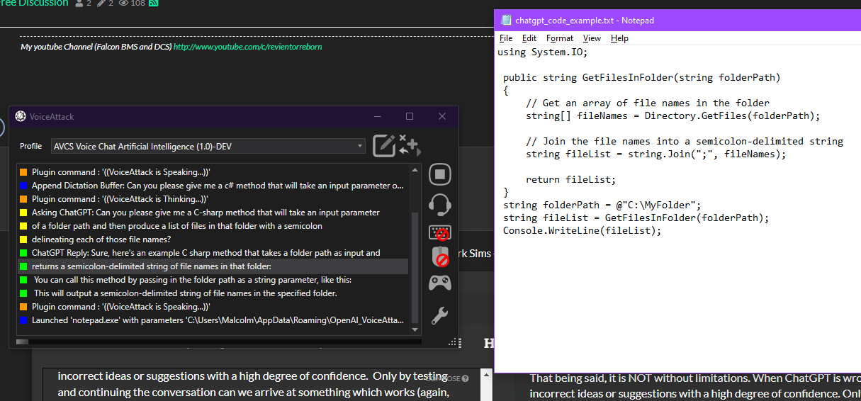
This is an example of what I've been working on for several months, only now finally almost ready to be released publicly - I can speak with ChatGPT and it responds with text-to-speech, like having a proper back-and-forth conversation with a real AI. I can even ask for code and my VoiceAttack profile will pull that out of the text-to-speech response so it is not spoken, and open it in a notepad! Coming this week!!

-
-
2
-
 1
1
-
 1
1
-
- Report
-

This is truly amazing!
-
-
 1
1
-
- Report
-

About to begin alpha testing phase for my latest project, bringing the power of artificial intelligence to the VoiceAttack program through a public plugin that any profile developer can use to create VoiceAttack profiles that make use of the OpenAI API and systems such as ChatGPT, Dall-E image generation/editing, and more:-
-
1
-
1
-
- Report
-
Please attempt all the methods offered in this thread to fix your issue. Clear your Shader Cache, and run SFC with DISM steps, and run the Safety Scanner. Report back when these are done, let us know the outcome (if they found files that are corrupt, etc.).
-
When Windows is not working correctly, you will want to scan the file system - like verifying the integrity of a Steam game install, but for the entire operating system. It usually takes around 30 minutes to run, or longer depending on the speed of the disk. SFC with DISM steps: https://support.microsoft.com/en-us/topic/use-the-system-file-checker-tool-to-repair-missing-or-corrupted-system-files-79aa86cb-ca52-166a-92a3-966e85d4094e To verify the safety and security of your Windows installation, use the Microsoft Safety Scanner: https://docs.microsoft.com/en-us/windows/security/threat-protection/intelligence/safety-scanner-download
-
Open the PR Launcher and click on Support - select the Utilities tab along the top and click the button to perform the Clear Shader Cache task at the top: Open Windows Disk Cleanup - Check the box next to DirectX Shader Cache and then press OK: ...try that and let us know if anything is better.
-
This is exactly what I did... 3000+ hours (not minutes) in VG PR COOP over 3+ years, I had enough and moved on. I got into Arma (2) and learned how easy it was to make anything we want in it with a little scripting, and into Falcon BMS where a pilot can spend years flying and only scratch the surface of the real operation of these fully simulated F-16's, and finally into proper programming for voice control systems in games, improvements for this website, our TCAdmin game servers web panel, and our dedicated game server(s) - even making my own hardware utilities and game controllers!! This hobby gets deep, don't ever get scope-locked on a single element such as PR COOP, or even PR in general. Even around here at VG, there are so many more things to get into and have fun online, from other games to team projects where we can turn our ideas into a reality that many people use. Even when PR COOP gets boring and 'the same old same old', I still find the PR Events fun to participate in when I'm able, and I hope that others who left PR would feel the same. It's still a great game, very well designed, and that's why it's still alive after 20 years - but the same can be said about Falcon BMS. The "good ones" last, and sometimes it's just a matter of finding these new "good ones" that can be (or already are) a welcome part to the VG online gaming community. After a certain time spent here making friends and hanging out, it is no longer about the games VG hosts or plays, but about the people we play games with at VG.
-
(It's "Sem" or "Semler" or "SemlerPDX", not Sam - lol, no worries) I've not had a chance to try this out, might be some weeks before I'm able to tinker with hardware again. When I do, I will try out your sketch and report back here. All my gear is put up, and not very convenient to pull out a at this time. I had a look over the code, and seems like it will work fine (obviously, it's working for you, so there's that). Take care and thanks again!!
-
if ever there was a need to find reasons to bring it back, this would be a frontrunner
-
Still hoping you will find some less cringy uses for AI cuz you're making me feel very smart, and I'm just a tinkering fool. Believe it or not, tools like this have been in use by MANY websites for ages to crap out articles, and even purposeful misinformation, and this example is nothing special IMHO (no offense intended, well ... not much, anyway).
-
Well done!! Congratulations! Any chance you could share your code for 3 encoders on 1 Pro Micro board? Pastebin is a great place to share code, or you could just use a code-block to paste it here. Might help the next person who happens upon this blog post and these comments.
- 42 comments
-
- 1
-
-
- dcs
- game controller
- (and 8 more)
-
i am unable to join a coop server
=VG= SemlerPDX replied to flyercrasher0's topic in Project Reality
Welcome to the forums bomber_678! You were banned on December 4th by our admin TH0M for improper vehicle use or waste. We like to give everyone the opportunity for a second chance if they've been banned, all we expect is honesty and that they agree to follow the rules in future (in most cases), and of course understand why they were banned in the first place so it doesn't happen again. You seemed to be new to the game, and our admins attempted to direct you as able for several days leading up to your ban. As you seemed to have not read or understood the rules of the game, that should have given you a forced opportunity to come here and read our PR COOP Server Rules. There's only 12, and it's pretty obvious stuff once you grasp some universal concepts of the game. Project Reality (even COOP) is a highly structured game, and you need to understand the basics at the very least before you assume all kits, vehicles, etc. are free for the taking by anyone at any time. This post may also help you understand the concepts of PR: https://www.realitymod.com/forum/showthread.php?t=134819 This is why you were eventually banned: [2022-11-28 14:22] !KICK performed by '=VG= batmeme' on ' bomber_678': Teamkilling of ANY kind is strictly forbidden! [2022-12-01 11:01] !WARN performed by '=VG= The_Polish_Guy' on ' bomber_678': You are not in the correct squad to use that vehicle! [2022-12-01 11:02] !KICK performed by '=VG= The_Polish_Guy' on ' bomber_678': steal and waste of trans [2022-12-01 11:40] !KILL performed by '=VG= The_Polish_Guy' on ' bomber_678': You are not in the correct squad to use that vehicle! [2022-12-01 11:50] !TEMPBAN performed by '=VG= The_Polish_Guy' on ' bomber_678': You are not in the correct squad to use that vehicle! [2022-12-02 16:41] !KICK performed by ' TH0M' on ' bomber_678': Your vehicle needs 2 people to operate! Return to base now! [2022-12-02 17:23] !WARN performed by '=VG= batmeme' on ' bomber_678': You are skipping flags! Fall back and attack flags in the right order [2022-12-02 17:29] !KICK performed by ' TH0M' on ' bomber_678': watch where you going [2022-12-04 12:47] !BAN performed by ' TH0M' on ' bomber_678': Vehicles must be used properly. Stop losing/wasting them! You will need to fill out an Unban Request if you wish to appeal your ban. As stated in our appeals: As a courtesy we look into all unban requests. The nature of the offense and the information you provide in your personal statement will determine the final outcome of your Appeal. We value honesty above all else! (the admin who banned you must also agree to the terms) We try to resolve all bans within 72 hours of the Appeal. All unbanned individuals will be placed on a watch list for 30 days. If any further issues occur during this time, your Ban will be reinstated and any future appeals will be denied...permanently. Thank you Project Reality - Unban Request Form- 1 reply
-
- 3
-
-
AVCS4 Voice Control Radios for Falcon BMS
=VG= SemlerPDX commented on =VG= SemlerPDX's file in VoiceAttack
 Glad you got it figured out! When I first released AVCS4 BMS, I didn't even realize I had to account for QWERTZ or AZERTY style layouts, even the difference in decimal number separators threw me for a loop. Thankfully, with feedback from users, I think pretty much everything we could want is covered by a voice command these days... you can even open a help menu (say, "Open the Help Menu") I greatly appreciate any support, my AVCS systems were literally hundreds of hours of work (with love) over a few years of development, and I'm really just getting started now that I've learned C# and even more about object oriented programming. Can't wait to redo all my menus with fancy GUI's like my AVCS SENS utility profile and even more optimized and efficient systems, applying what I've learned since 2019. I have a personal paypal link here: https://veterans-gaming.com/semlerpdx/donate/ ...and also a "Buy Me a Coffee" link here: https://www.buymeacoffee.com/semlerpdx
 -
Hello and welcome back! Welcome to the VG Army!
-
AVCS CORE Server Not Available? (SOLVED)
=VG= SemlerPDX replied to machtoo's topic in AVCS Discussion & Support
The AVCS CORE Server is this website, so if you can post here, it's online. Make sure you are running VoiceAttack as Administrator, and restart it - switch to AVCS CORE, and it should initialize straight away. Use the option under the System / Advanced tab of VoiceAttack options to enable this: -
X52 Pro - Falconeer Joystick Profile for BMS
=VG= SemlerPDX commented on =VG= SemlerPDX's file in Saitek X52 Joystick Profiles
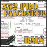 One user had issues in BMS 4.37 when trying to use the X52 Pro Falconeer profile, and this is how it was resolved:
 -
I made a command line tool... I had fun.....
allows us to remotely recover the VG BMS server when it does something dumbz like commit 40GB of memory for the BMS server process. Now we can plod along until the next patch update fixes this known memory leak issue. Fun fun
now I'm gonna go pass out zzzzzzz....-
-
2
-
- Report
-
Parts List & Links Preparing the Sensor Preparing the Case Preparing the Arduino Final Assembly Uploading the Code Get Help & Support I have written a new voice control profile called 'AVCS SENS' for VoiceAttack specifically dealing with sensors and weather commands. I wanted to use the Shared Memory feature of the AIDA64 Extreme sensor monitoring program to enable my VoiceAttack profile to speak the requested computer sensor value when asked over text-to-speech. Once I had sensor values from AIDA64 Extreme in VoiceAttack, I then added a DHT11 Temperature & Humidity sensor to the Arduino Uno on my prototype breadboard, connected to my PC through USB. Now reading this as well from my VoiceAttack profile, I could do a little math to get a more absolute and objective value from the computer sensors, a CPU temperature in "degrees over ambient", for example, or "delta-T over ambient" as you may hear it called in analysis videos such as this one here talking about case testing methodology used by Gamers Nexus. This is the true means to understand what computer sensors for temperature are reporting at any given time, by first accounting for the temperature of the room. Finally, with this relative sensor data now available, I've been able to write a simple diagnostic algorithm which can identify & flag atypical sensor values, as compared to stored baseline values on file, for voice commands in VoiceAttack. Without an AVCS-DHT1, outdoor weather and sensor report commands are still available, yet indoor weather & sensor diagnostic commands will be unavailable. I wanted to make it possible for anyone using my new AVCS SENS profile for VoiceAttack to either be able build their own AVCS-DHT1 USB external temperature & humidity sensor, or buy one designed & built by me, according to this simple Arduino project build guide, and therefore unlock these additional voice command features for AVCS SENS. My DIY USB Temperature & Humidity Sensor 'AVCS-DHT1' - for use in my AVCS Voice Sensors & Weather Profile parts list below contains links to specific items which I directly purchased myself for this project on Amazon only, but any store will do, and also any equivalent part which performs the same will work (brand names/quantities do not matter!) if you are using a different case than the exact one linked below, or other components, please see the note in the AVCS SENS Wiki page regarding Sensor Calibration Project Required Parts List (all prices listed in USD - price and availability may be different past last publish date of this guide) Arduino Nano (or equivalent clone) - with NO header pins soldered on! (HiLetgo Nano v3.0 5V) (3 pack) - $24.49 https://www.amazon.com/dp/B01DLIJQA2 $8.16 per board USB Cable - USB 2.0 Type A to Mini-B (3ft. or 1 meter, at least) (or equivalent part) (iSeekerKit Nylon Braided 3ft.) (3 pack) - $8.99 https://www.amazon.com/dp/B08LL272SK $3.00 per cable DHT11 Temperature Humidity Sensor Module 3.3V-5V (or DHT22, or equivalent part) (HiLetgo w/Dupont Wires) (5 pack) - $10.29 https://www.amazon.com/dp/B01DKC2GQ0 $2.06 per sensor Plastic Electronics Project Case @ 1.97" x 1.10" x 0.59" (50mm x 28mm x 15mm) (Zulkit ABS Project Boxes) (5 pack) - $7.99 https://www.amazon.com/dp/B07PZ24LFD $1.60 per item Metal Film Fixed Resistor 10K ohm (0.5Watt) - just one will be needed (EDGELEC Pack of Resistors) (100 pack) - $5.99 https://www.amazon.com/dp/B07QJB31M7 $0.06 per resistor Strong Double-Sided Foam Adhesive Tape (or equivalent product) - only need a few inches (Gorilla Brand Heavy Duty Mounting Tape) (1" x 120" roll) - $11.34 https://www.amazon.com/dp/B082TQ3KB5 $0.20 approx. amount used Neodymium Magnet 8mm x 2mm (round, size is important!) - just one will be needed (FINDMAG Box of Magnets) (100 pack) - $9.99 https://www.amazon.com/dp/B09BB1VT4J $0.10 per magnet Total: $15.18 (USD) (for 1 sensor*) - (total if all parts purchased with amounts above: $79.08) *(also required - drill/rotary tool, solder and soldering iron, electrical tape, tweezers, scissors, 'nippers', 'spudger' type tool, and SuperGlue) This project requires the following skills & knowledge: Basic understanding of Arduino (what it is/what it does) Basic experience with electrical soldering Basic skills with drill or Dremel/rotary tool and bits Use of and precautions relating to SuperGlue type adhesive Ability to make precise cuts with scissors within 1-2mm Ability to carefully follow instructions (some are crucial) Entry level experience with VoiceAttack (import profile, etc.) Ability to work w/ tiny parts in a small space in timely manner A positive attitude and willingness to adapt and overcome (not exactly required, but always recommended ) Part 1 - Preparing the Sensor preparing the DHT sensor and stripping the braided wires - image a1 1. Separate the DHT11 (or DHT22) from the breakout board it is mounted on (if not supplied without one). Either snip the wires from the DHT as close to the board as possible with "nippers" (image a1), or de-solder them from the breakout board. If supplied with the Dupont ribbon wires, remove the plastic ends and prepare the wire ends by cutting them even and strip the wires leaving at least 1.5cm bare. We want around 75-100mm (2.95-3.93") of flexible braided wire so we can zig-zag the excess, allowing us to remove the plastic lid with sensor and not risk yanking the soldered wires out. solder wire ends - image a2 2. Twist the wire ends and tint them with solder to make them stiff, yet not so much as to increase their width with too much solder & slag - three of them must fit through the holes on the Arduino. 3. Once the DHT has been separated from the breakout board, with the side with holes facing you and pins down, cut the third pin from the left, or second from the right, as in image a1. gently bending the pins, resistor legs, and wires - image a4 4. Prepare the DHT pins by gently curving them into hooks facing away from the side of the sensor with holes. Gently bend the legs of the 10K ohm resistor (as shown in image a4) so that it will sit in the hooks of the two DHT pins closest together, as seen with the sensor face down (holes down, as in image a5). resistor placement - image a5 5. Bend two of the three wire ends away laterally away from the third wire, into a gentle hook shape, and the third wire opposite those in the same manner. Lay the 10K ohm resistor into the right two wire-hooks of the DHT sensor (face down - image a5). final goal for the resistor, legs, and wires: flat & straight - image a3 NOTE: The Resistor should be offset in a manner where its bulk and width can mostly lay flat along side the wires and not on top of them once completed (image a3). gently crimping the DHT pins around resistor legs & wires - image a6 6. Lay the wire "hooks" into their corresponding DHT wire "hooks" over the resistor, and if able, use a tweezers to gently compress these DHT wire hooks to contain the wires and resistor for soldering, as well as the wire "hooks" themselves. If this is not possible, you may want to secure the DHT to the table with scotch tape, lay the three wires in place in their "hooks", and scotch tape down the wires to the table with a gentle pull, to ensure they remain in place while soldering them firmly in place as one connection. soldering to the DHT - image a7 7. Solder each connection so that the wire, the wire "hook" from the DHT, and the resistor are fully encased, and not touching each other. trimming legs from resistor, and any protruding slag - image a8 8. When cooled, use "nippers" to nip any protruding slag or wire ends, and the trailing legs of the resistor as it exits the solder as in image a8. The wires should travel flat following the rear plane of the sensor, so that later, the front face of the sensor (with holes) can protrude out of a hole we will cut in the case lid. Refer to images a3 and a8 to see the resistor in-line with wires, as an example. wrap wires separately - image a9 9. Finally, wrap each exposed solder point with a separate small piece of electrical tape to ensure each cannot bridge contact with another in the event that something gets bent. Just sandwiching a small rectangle of tape over each one will do, even if each has a tail of tape hanging off. These bits of tape will be covered and held in place permanently once the sensor is mounted into the lid later. SAFETY SAVES LIVES - SAFETY GOGGLES SAVE EYES! BE SMART AND USE APPROPRIATE SAFETY GEAR WHILE WORKING! Part 2 - Preparing the Case drill 12 tiny air holes - image b1 1. Carefully remove the lid from the case - while holding the base in one hand, lid up, with the notch in the lid away from you, use a fingernail in the notch along with pressure from your finger to pry that side of the lid upwards. If using a tool, be careful not to use too much pressure or the soft ABS plastic may deform or scratch if the tool jumps too fast once the lid becomes free. keep notch at bottom - image b2 2. For the lid, we want to create a rectangular hole that will allow the front face of the DHT sensor to protrude. The tapered sides of the blue sensor case widen towards its back which will keep it from protruding farther. The lid is 25.9mm wide & 47.75mm tall. The approximate width of the hole will be at or under 16mm tall and 12.60mm wide. For this to work well, it is best to cut a slightly smaller hole than desired and slowly widen it with hand tools or low speed rotary tool - stopping and testing the fit until just right (as shown in image b6 below). It is not easy to get exact, I've tried. Just accept any slight tilt, it is a DIY after all. port is upside down - image b3 The goal for the USB hole is to make it flush with the bottom of the case as it exits, and as wide as the USB port itself (8mm). The port is 4mm tall, but as you can see in image b3, even I could not quite keep that height with that limit as I drilled and widened the hole. Again, stop and check the fit - first dusting out any bits of plastic from the process, and sliding the Arduino Nano upside down as shown for a test fit. It must slide flat with the case bottom and through the case wall as shown. 3. With the lid removed from the base, use a drill bit between 1mm-2mm at low speed to create 4 holes in the 'top', and 4 holes on each side near the top (as shown in image b1), for 12 total air holes. The passthrough hole for the USB mini-B port will require drilling and widening with hand tools or a rotary tool at a low speed. The port is about 4mm tall & 8mm wide. High speeds may heat and melt the ABS plastic, so if you are working at an area for too long, back off and let it cool down. place one small drop of SuperGlue at the arrow for magnet - image b4 4. Once all the holes are drilled and the rough edges cleaned up as much as possible, wipe the interior clean of plastic dust. Using a strong SuperGlue, place a very small drop inside the case at the top near the four holes you drilled, as shown by the arrow in image b4. Carefully place the tiny magnet over the drop of glue; non-magnetic tip tweezers or even chopsticks can really help - just be sure not to touch the SuperGlue as you position the magnet. test fit the sensor into lid - image b6 5. Finally, cut a strip of the double-sided adhesive foam tape about 25mm wide and 8mm tall - do not remove the backing yet! Once the SuperGlue has dried (give it a few minutes) place the strip of tape over the magnet (image b5, below). fully cover magnet with tape, do not remove backing (yet) - image b5 Part 3 - Preparing the Arduino setting the board to "Arduino Nano" and its COM Port - image c1 1. Open the Arduino IDE v1.8 (latest) (download and install first, if not already done) and make sure it is updated to current release version. Place the Arduino Nano on a hard, non-conductive surface, and connect the USB cable to the device and then to the PC. Refer to device instructions (per brand/model/type) as required, if the device driver is not installed automatically. Under the 'Tools' Menu along the top, select the COM Port of this device, and set the board to Arduino Nano (as shown in image c1), and unless directed by device instructions, leave the Processor as "ATmega328P". opening and uploading the Arduino Basics "Blink" sketch - image c2 2. Under the 'File' Menu along the top, select Examples > Basics > Blink to open this sketch (see image c2). Next, click the Upload button ( ) to send this sketch to the Arduino Nano. Verify that the onboard LED slowly blinks on and off repeatedly to ensure this board is functioning, and that sketches are uploading properly. If you have any problems at this stage, you will want to stop and perform other troubleshooting steps to verify that the Arduino IDE is set up properly to communicate with this board, and that the board itself is not faulty. See Addendum at the bottom of this guide for help. installing or updating the "Adafruit Unified Sensor" library - image c3 3. To get data from the DHT sensor, we will be using an open source DHT Sensor Library by Adafruit, which requires the Adafruit Unified Sensor Library, as well. In the Arduino IDE, under the 'Tools' Menu, select 'Manage Libraries...' (or press CTRL+i) to open this window - it takes a few seconds to open. First, select the Type of "All" (if not already selected), and the Topic of "Sensors". In the search field, type "Adafruit Unified Sensor". The list will be long, scroll down until you find the Adafruit Unified Sensor library (as pictured in image c3) - install it or update with the latest version, if not already. installing or updating the Adafruit "DHT sensor library" - image c4 4. Next, in that same search field, type "DHT sensor library". Again, the list will be long, scroll down until you find the item with the title "DHT sensor library" by Adafruit (as pictured in image c4) - again, install or update it if it is not installed with the latest version. When you are finished, close the Library Manager and disconnect the Arduino from the computer. If desired, use a light grit sandpaper on the edges of the Arduino Nano PCB board to make them smooth. AVCS-DHT1 Wiring Diagram (your resistor color may be different!) - image c5 5. Once you have verified that the Blink sketch is working from earlier steps, and that the Arduino IDE can properly upload to the Arduino Nano board, it's time to solder the wires from the DHT sensor to the Arduino. Follow the wiring diagram (shown in image c5), separating the ribbon cable to individual wires for flexibility, as needed. later, mounting will be upside down, as shown here - image c6 NOTE: As stated before, the Arduino Nano MUST be upside down (shown in image c6) in the end. You may wish to do as I have done, and push the wires through from the other (top) side of the board, soldering them into place on the underside (now facing up, like image c6). Unlike the diagram, the brown wire from these pictures is the black/ground wire, the red wire is the yellow/signal wire, and the orange wire is the red VCC/5V from image c5! Your wires may differ in color as well, if using those supplied with your DHT module as I have done. Do not get them mixed up - follow any wire back to the DHT to identify it properly. When complete, trim any protruding slag, or excess length from the wires as they exit the board, once cooled. Part 4 - Final Assembly gently press down on areas such as those noted with arrows - image d1 1. Cut a piece of the double-sided adhesive foam tape 23mm wide and 45mm tall, with a small notch cut out to allow wires to pass as shown in image d1. Do not remove the backing to expose the second adhesive side, this backing will remain on permanently as an additional barrier between the sensor, the Arduino, and the wires in the case. 2. Place the completed sensor and wires assembly into its slot you cut out in the lid, from the inside. Cover the entire unit with the tape you cut out, allowing the wires to fit through the notch. Use a dull plastic "spudger" type tool (image d1) to gently but thoroughly press down at all contact points, bends, and flat areas where the tape should make full contact with the lid and sensor. Avoid the area of the wires and resistor, and the soldering points - use only a finger or thumb and gentle pressure in the area over wires to ensure a light contact. We don't want to break any of the solder or unintentionally bridge the contacts. Do the same for the tape covering the magnet in the case - press into the bends and flat areas to ensure permanent contact. Do not compress the part on the top of the magnet too much - we need this pile to be between 3-5mm to make contact with the Arduino Nano when it is finally in place. first remove backing from tape, then apply the SuperGlue - image d2 3. Before proceeding, with the protective backing still on the tape covering the magnet (still "un-sticky"), test fit the Arduino Nano into the case one last time - make sure the USB port sits flush with the base of the case as it exits, and the PCB board is flush with the edge of the case with the USB port hole (such as in image d3). Ensure that the back of the Arduino overlapping the magnet touches the tape and the peel covering it - this is the last chance to make it taller with another bit of tape, if you used a different or thinner type of tape not recommended by this guide. It should be a foam type tape with some give, and adding to the height of the magnet enough to make contact with the Arduino (about as tall as the USB port on the other side, 4mm). When ready, first remove the backing peel entirely from the double-sided adhesive covering the magnet - a sharp pair of tweezers can help here, it is NOT EASY and your luck may vary (condolences, I use this stuff all the time because it is so great, but for this one flaw - actually getting the backing off once it's in place can be painful!). Once you're done fighting the Gorilla tape and got the backing peel off, place a small dot of SuperGlue inside the case near the USB port passthrough hole. In the example image d2 there is almost too much, half this much would do - you can use a cotton swab to soak up some of the glue before it dries, but this entire procedure must be done swiftly. Before the SuperGlue dries, very carefully slot the Arduino Nano into the case at an angle, with the USB port first, keeping the back from touching the tape yet - slide the Arduino USB port through the hole and then lower the back end down into position above the tape, keeping the PCB flush with the case wall, and the USB port through the hole as it makes contact with and compresses the SuperGlue. Quickly dab up any SuperGlue that may leak out of the hole and outside the case. apply light pressure on right and strong pressure on left - image d3 4. Referring to image d3, with light & gentle finger pressure, press down on the area noted by the arrow on the right, while also using a more firm finger pressure to press down on the area noted by the arrow on the left (over the tape/magnet). Be sure not to put a lot of pressure on the right where those components are, it is not necessary - the SuperGlue will do its job, we just need to give it light pressure to help spread the SuperGlue and ensure flush contact as we put greater pressure on the left where there are no components and we want full contact with that tape. fully assembled - image d4 5. Before closing the lid, allow up to several minutes for the SuperGlue to dry. Take this time to plan the bends or separations in the ribbon wire (if using one) so that each wire can sit in a sort-of zig-zag fashion once we do close the lid. In image d3, the wires are actually a bit long and will require an extra 'zag' to fit, so I have separated the wires nearly to the first bend. The first bend by the lid and notch in the tape must be acute & firm without crimping! Once the SuperGlue is dry, carefully guide the wires into places they won't impede as you close the lid - start from the far end away from the wires, and lower it into place over the USB port side lastly. Be careful not to force it closed, adjust as needed to ensure a tight fit without jamming the wires into hard crimps or bends which could sever tiny wires in the braid inside the wire jacket. The Official AVCS-DHT1 sticker label - image d5 6. The AVCS-DHT1 Sensor (being magnetic) is designed to stick to a PC case in a vertical orientation somewhere not far from the intake, but far enough from intake fans to not be 'cooled by the wind'. The back of the ABS plastic case on the sensor can potentially mar or scuff softer paint on a PC case, so it is advised to place a piece of black electrical tape or even Scotch Tape along this surface simply to ensure a softer contact with the PC. All AVCS-DHT1 sensors built by me and sold in the VG Store will have this sticker label (shown in image d5), which also serves this purpose as a softer backing to help avoid minor scuffing over time. If using one of these labels, carefully cut around the grey box on the label leaving about a 1-2mm margin as shown. You may consider peeling back and folding a crease in the wax paper backing, then folding back into place over the adhesive surface, before cutting the label to size - this will help more easily remove the backing once you've trimmed off the edges of the label. Unlike the high cost of shipping pre-built sensors around the world, I can offer these cool little AVCS-DHT1 sticker labels to anyone following this DIY Build Guide for a fairly low price in the VG Store including free domestic and international shipping to around 180 countries. It's much cheaper to mail a small envelope than a box, of course. Click Here to open the VG Store in a new browser tab to check out these sticker labels. Part 5 - Uploading the Code AVCS_DHT1_DIY_Sensor_v3 7. At long last, we can upload the Arduino sketch to the device and get some sensor data onto the computer! Start by connecting the AVCS-DHT1 sensor to the computer with the USB cable, and mount it as noted, on the front or side of the computer near the intake but not within range of wind created by intake fans. The area of the panel where the sensor sits should not be near any internal components which get hot under heavy PC use. 8. Open the Arduino IDE program again. Under the 'File' Menu, select 'New' (or press CTRL+N) to create a new sketch called "AVCS_DHT1_DIY_Sensor_v3". Select the entire contents of this new sketch and delete them so you have a blank text area to paste into. Next, Expand Contents of the code block above - copy the entire contents of the code block here from line number 1 through line number 86. You can copy the code block to your clipboard more easily by clicking the "Download Raw" button provided by Pastebin, and select all the text on that page & copy it. Finally, paste the entire code into your sketch in the Arduino IDE (overwriting any contents) and save the sketch (CTRL+S). Now we can upload the sketch from the Arduino IDE program to the Arduino Nano by pressing the ( ) upload button just as we did with the Blink sketch above. When uploading is done, close the Arduino IDE program and proceed with testing at step 9 below. If you see any problems in the errors and information window below the sketch when trying to upload and if the title bar over this information window at the bottom of the sketch does not show the words ( ) when done, stop and get Help or Support from the links in the Addendum at the bottom of this guide. AVCS SENS profile version shown above may differ from latest - image e1 9. Launch the VoiceAttack program and switch to the AVCS Sensors & Weather Profile (if not already running and loaded). When voice commands are available, say, "Open the Sensor Menu". The AVCS SENS Main Menu will pop up. Press the "OPTIONS" button, and then press the "Sensor Options" button. In the Sensor Options screen, press the "Test Arduino DHT11 Sensor" button - there will be a voice reply of either "Test Succeeded" or, of course, "Failed". Upon a successful test, the VoiceAttack Event Log (shown in image e1) will display several text messages, including a sample of the data received such as: AVCS-DHT1 Data: [AVCS,22.75,65.00,72.95,73.00,DHT1] DHT Monitoring in AVCS SENS is a secondary monitor tied to the Sensor and/or Weather Monitor. If either of these are started, DHT Monitoring will try to start. If no DHT sensor is detected, indoor weather & sensor diagnostic commands will not work. If both Sensor & Weather Monitoring are turned off while DHT Monitor is on, the DHT Monitor will also turn off. Congratulations on successfully building an AVCS-DHT1 Sensor! Enjoy the indoor weather & PC sensor diagnostic voice commands! *alternatively, if you were not so successful, please see links below in the addendum for help & support on a variety of topics. I am also happy to provide assistance here if you would like to reply below, or through private message here or on Discord - whatever is preferrable Addendum - Help & Support for this DIY Arduino Project If you need help, post up a reply below and I'll answer as soon as I see it. Otherwise, here are some helpful links pertaining to this project: AVCS Help and Support Links AVCS SENS Profile Download AVCS SENS Wiki Page AVCS Help Channel on Discord AVCS Bug Reports Contact SemlerPDX Arduino Links Arduino IDE Download Arduino Guide Arduino Help Center Arduino Forums Arduino Discord VoiceAttack Links VoiceAttack Tips & How To VoiceAttack Manual VoiceAttack Product Page VoiceAttack Forums VoiceAttack Discord "AVCS SENS", including the Profile Package for VoiceAttack, the AVCS SENS Wiki page, the AVCS-DHT1 Sensor and Sticker Label, and this DIY build guide, comprise creative works by SemlerPDX shared under CC BY-NC-ND 4.0 March/June 2022 AIDA64 is not affiliated with AVCS or this DIY project. Images and text depicting the AID64 program(s), title, logo, or other elements belonging to AIDA64 or FinalWire Ltd. are used only for educational and/or instructional purposes, relating to demonstration & use, in this DIY project guide. AIDA64 is a Registered Trademark of FinalWire Ltd. ©2010-2023 All rights reserved.